
Examples of Equipment Development
Cetry helps medical device manufacturers and their suppliers by means of problem solving, process modelling, characterization of product properties, device and materials qualification, process and manufacturing validation, related regulatory issues, quality assurance, and design and build of specialized equipment. Here follow some examples of equipment that was designed and/or built by Cetry.
List of Examples:
Plasma reactor - medical device treatment and research
| • Client: | Major manufacturer of diagnostic and interventional catheters, stents and accessories |
| • Subject: | Dual purpose plasma reactor |
The client requested the build of a plasma reactor for purpose of pilot- and small-scale regular production, as well as research. The latter included plasma-induced coating deposition. No side effects due to cross-contamination or equipment fatique were allowed. The system was designed with 2 glass reactor tubes, of which one was designated for production and the other for research. The gas-inlets were seperated too, in order to avoid residual process gasses to end up in the wrong tube. It was not possible to use the two reactor tubes simultaneously. Protocols were put in place regarding use and maintenance of the reactor. In-process controls secured the production side of the matter. The design involved a 300 W RF-generator, running at 13.56 MHz. Electrode design was optimized for maximized gas-excitation levels. Processes could be run at pressures down to 0.5 Pa. Membrane manometers were used to enable pressure readings independent of gas type. Methods and protocols for in-house calibration were provided (validated). The reactor has been used for (1) surface treatments (inner- and outer surfaces) for coating and increase of coefficient of friction, (2) layer deposition, (3) etching. After several years, the design was enhanced with a roots-pump, in order to allow faster cycling and more intense de- and outgassing of polymer-based products. The plasma reactor is still in use to date, now only for large-scale production. The entire design was duplicated for extended production capacity.
return to top...
Plasma reactor - manufacturing
| • Client: | Start-up manufacturer of diagnostic catheters |
| • Subject: | Plasma reactor for improved bonding |
This reactor was built for polymer-surface treatments only; production use. The design consisted of a single 75-liter vessel with simple in- and outputs. Special care was given to corrosion protection, down to the level of the pump oil. Fast cycling was obtained by use of a short (thick) vacuum hose between reactor and pump, and by using a 80 m3/hr two-stage rotary vane pump. The gas system incorporated two precision mass-flow controllers, and vacuum was monitored by a simple bourdon manometer for pump-down and a membrane manometer for the low processing pressures. Processing methods were validated, and processed medical devices passed the qualification criteria. Production capacity sufficed.
return to top...
Plasma reactor - Cetry in-house
| • Client: | Cetry |
| • Subject: | Plasma reactor for in-house use |
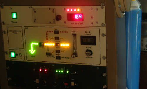
A reactor was designed and built with the aim of providing services to various clients as well as in-house research. The design involved multiple feedthroughs, thus allowing insertion of measuring devices (e.g. temperature sensing) and an in-house designed heater. Vacuum is provided by a simple two-stage rotary vane pump. The gas discharge is powered by a variable frequency in-house designed and built 100-Watts generator. Frequency range: 70 kHz - 300 kHz; continuously adjustable - read-out on a built-in frequency meter. The reactor has been used for various tests by several clients, who e.g. did not want to break in on the capacity of their own production reactors. Examples of use are: Outgassing experiments on medical materials, treatments for coating adhesion enhancement, treatments for increase of the friction coefficient of medical devices and accessories. The photograph at the top of this page shows a detail of the plasma reactor that is being used for in-house research.
return to top...
Automated dip-coating equipment
| • Client: | Major manufacturer of diagnostic and interventional catheters, stents and accessories |
| • Subject: | Automated dip-coating & drying equipment |
Coating was to be applied to both the outside and the inside of diagnostic catheters. It concerned multiple processing stages, including rinsing with purified water. Some chemicals were not allowed to come into contact with each other. The chemicals were also quite expensive, so that neither dilution effects from the rinse water nor degradation due to storage were allowed. The equipment should not only hold sufficient capacity but also have low down-time for cleaning and preventive decontamination. Handling should be minimized, both from the view of personal hazzard and processing speed. A machine was designed that fit the nature of the chemicals and the processing demands given. It basically consisted of several huge "test-tubes" that could be filled and drained from the bottom either in serial or parallel operation. An elaborate piping & valve system handled all the liquid flows and storage. The whole system was computer controlled, except for product mounting. The computer software was lenient towards hardware errors; it traced the error (e.g. low vacuum or pressure) and would then decide what action could keep the process running within the limits of its validation window. This method of "intelligent processing" allowed for more continuity during processing and less down-time in between. The program included options for "manual" operation, step-sequencing (one process step at a time) and always kept track of valve operation, vacuum, pressure and liquid levels. The equipment was successfully qualified and put into production.
return to top...
Semi-automatic catheter fusing equipment
| • Client: | Start-up manufacturer of diagnostic catheters |
| • Subject: | Semi-automatic catheter fusing equipment |
RF-induced fusion of rod-mounted plastic tubing allows for electronically controlled processing. Think of relay-controlled on/off timing and ease of power management. It also uses much less energy than fusion by means of a permanently heated die. The existing equipment consisted of a single timer with a single RF generator. Most of the processing time was spent on catheter mounting and removal; one at a time. A simpler catheter holder was made, allowing for fast mounting of up to eight pieces of catheter tubing at a time. Also, eight identical induction coils were made and mounted on a slider so that instead of putting the catheters into the coils one by one, now the coils were slid over the catheters and covered them in one single movement. The inductors were fired one by one, like a machine gun, since parallel firing could not be sustained by the generator. The number of channels-in-use could be set manually, between 1 and 8. The catheters could be dismounted simply be moving the slider with the coils out of the way; all fuses ready. With this machine and processing method, catheter assembly on the whole was significantly speeded up! It effectively freed up 0.5 fte.
return to top...
Static friction meter
| • Client: | Cetry |
| • Subject: | Precision static friction meter for in-house use |
Being specialized in development of medical coatings, Cetry aims to offer complete analysis. Most analyses are done on site, with the client's own equipment. Biocompatibility is done by specialized firms. However, precision static friction testing is most often not available, despite its great value. It offers a fast way of comparing friction between almost any set of surfaces, wet or dry. The static friction meter comprises a motorized tilting table and a angle measuring device. Tilting can be done at any desired speed. Automatic return to zero at relatively fast speeds allows for improved (faster) workflow. Resolution: 0.2 degrees. The equipment was used during the in-house development of the EMPEH coating (see PRODUCTS), for a PTCA-catheter manufacturer, and for an IOL developer.
return to top...
Specifications of UV curing cabinets
| • Client: | Major medical device manufacturer |
| • Subject: | Design parameters for two different UV curing cabinets |
Cetry was hired to specify equipment features for curing cabinets that were to be used for UV-curable hydrogel coatings. It was clear that the manufacturer of the UV-curable coating material was not able to correctly specify the UV lighting properties that would go with optimized processing. Cetry had already been asked to look into coating integrity fluctuations that had led to undesired variation in medical device performance. Physics and chemistry of the UV exposure were examined, which resulted in a new and very specific set of lighting parameters. One of the problems was found in temperature elevation during processing, another in the relationship between exposure intensity and exposure time. Reflective surfaces were optimized, in order to make sure that every coated part received sufficient UV dose. Another aspect was found in the strong belief that UV exposure and curing were the same thing. Thus, it was believed that curing was expected to be done, right after the UV exposure. However, the curing process is only initiated by the UV exposure, and it may sometimes take days before the end-result can be judged. So, part of the inability to solve the problem was found in the fact that testing was done immediately after UV exposure, when the coating was not fully cured, yet. Correct testing led to well-specified sets of features to be implemented in the UV-cabinet designs. Now the coating quality is stable and coating performance is optimal.
return to top...
Thermoplate for use in vacuum
| • Client: | Cetry |
| • Subject: | Hot-plate for use in vacuum |
Vacuum drying of polymeric materials can be enhanced by heating. With hardly any air in the vacuum chamber, heat transfer is to be done by infra-red radiation and/or by direct contact between the hot-plate and the material. One can heat the entire wall of the vacuum chamber, but that takes a lot of time and energy and is not always very controllable at the location of the material. Cetry designed and built a small low power sensor-controlled hot-plate with infra-red reflectors (shielding), which allows for direct contact with the material, local temperature monitoring, and heating up to 90 degrees Celcius. It has been used for drying of polymeric biodegradable materials and hydrogel components, sometimes combined melt-drying, outgassing, etc.
return to top...
Table-top deposition reactor
| • Client: | U.S. manufacturer of stent delivery systems |
| • Subject: | Table-top plasma reactor for coating deposition |
The R&D department already owned a research plasma reactor, featuring a flexible vacuum routing system. There was need of a new reactor chamber that would fit a table-top and at the same time have sufficient (pilot) manufacturing capacity. It should be connected to the existing system, without disabling any of the existing functionalities. A glass "baby-reactor" was designed and assembled, including trays and feedthrough facilities. Many experiments have been (successfully) conducted with this piece of equipment. It was easy to clean (e.g. by means of plasma etching) and loading/unloading was a cinch. Coating deposition homogeneity was greatly enhanced with respect to the old situation. Capacity and processing speed were more than adequate.
return to top...
Low-budget cleanroom
| • Client: | Starting manufacturer of medical devices |
| • Subject: | 100 m2 of class 100,000 cleanroom |
Cetry calculated and designed a cleanroom that should not exceed class 100,000 requirements. With plenty of second-hand ventilators and high-efficiency filters made available by the client, this case proved to be quite some fun. Air flow was assessed - think of refresh rate, spreading, etc. - and all sorts of other parameters were considered, such as heating, movement of personnel, placement of work benches, cleaning method and frequency, and a practical airlock design. The whole construction was qualified, and it also passed the scrutiny of the Notified Body. Qualification included particle counts and microbiological activity as function of the number of people working in the cleanroom, as function of the day of the week, cleaning, and so on. The cleanroom generally scored better than class 10,000 and had a high recovery speed (particle count comparison between cleanroom filled with people versus vacated). Recovery was sufficient to allow reduction of the refresh rate at night, thus saving lots of energy. This nightly "eco-mode" also passed qualification.
return to top...